
 Vibration in rotating machinery is generally measured using several independent, strategically mounted accelerometers. However, a more effective option is to use triaxial accelerometers that measure vibration in three orthogonal axes, says Hansford Sensors’ MD, Chris Hansford.
Many companies that rely on machines for their production will have installed some form of machine condition monitoring technique to help them identify early signs of an impending failure so that they can act before a machine breaks down altogether and thereby avoid the costs of lost production. Along with temperature, the most commonly measured parameter in any machine condition monitoring scheme is vibration.
All machines vibrate, regardless of how precisely they have been constructed, installed and subsequently operated; and, of course, they don’t just vibrate along a single axis. A pump, for example, has a multi-modal vibration signature representing the combined effects of case resonances, rotor imbalances and the complex hydraulic interactions between pumped fluid and impeller. In order to gain an accurate assessment of this signature, vibration must be measured in several key axes.
Vibration measurement relies on the deployment of sensitive accelerometers, which are mounted at strategic locations on the machine, such as bearing housings, pump casings, gearboxes, to measure vibration frequencies and amplitudes in any number of machine axes. These signals are subsequently analysed to identify departures from a machine’s ‘ideal’ vibration signature that may be indicative of impending malfunction – a developing defect on a bearing raceway or pump impeller damage, for example.
Installing multiple accelerometers, one for each of the axes that requires monitoring, can be a complicated approach, as the outputs from each sensor must be combined in phase to produce a meaningful assessment of the condition of the machine being monitored. As a general rule of thumb, the more complex the data analysis, the greater will be the risk of error. Moreover, if space or access is restricted, then fitting multiple separate units may be impractical at best, impossible at worst; multiple units also add weight (which will affect the acceleration measurement if more than 10% of the weight of the monitored object) while increasing cabling complexity.
A more effective option is to use specialised triaxial accelerometers which are compact and lightweight and are capable of simultaneously measuring vibration in three axes, providing a single integrated output for quick and accurate phase analysis. Like all precision devices, however, careful location and calibration is critical if accurate and consistent results are to be obtained from a triaxial accelerometer installation. But what exactly is a triaxial accelerometer?
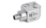
Triaxial accelerometers integrate three separate accelerometer sensor assemblies in a single housing to provide simultaneous and independent dynamic measurements of acceleration in three orthogonal axes (X, Y, and Z). They are commonly housed in miniature cube shaped enclosures made from aluminium, stainless steel or even titanium, with a single M12 4-pin connector and some form of mounting arrangement such as a stud or threaded receptacle. Hansford’s HS-173 Premium triaxial accelerometer, for example, provides three ac outputs with virtually flat responses from 2Hz to 10kHz, a wide operating temperature range from -55°C to 130°C and IP67 sealing. This particular sensor will also tolerate shock levels as high as 5,000g.
An arrangement of three separate single-axis accelerometers fitted to a triaxial mounting block will achieve the desired measurements in three orthogonal axes, but this carries some major disadvantages, not least being the space taken up by such an arrangement, its substantial additional weight compared with than of a miniature integrated three-axis sensor and a near threefold increase in cabling requirement.
Positioning and mounting
While single axis accelerometers can be mounted in separate locations, selected in order to detect vibration in specific axes with minimal noise interference, triaxial units have just one mounting position. When locating these types of sensor it is therefore important to consider their orientation and determine an optimum position on the machine casing, which may involve an element of trial and error. Where positioning is concerned, it is often useful to gain advice from sensor manufacturers who will have a wealth of applications experience to call upon to assist you.
Correct mounting is arguably more critical than positioning as the effective coupling of the sensor to the monitored target will ultimately determine the quality of the accelerometer signal obtained from the installation – particularly its frequency range. Common mounting methods include the use of cyanoacrylate adhesives or magnets and for more permanent installations, threaded studs, which enable the sensor to be screwed into the machine casing and tightened to a predetermined torque.
Generally, the most rigid and lightweight method of mounting should be sought to ensure adequate coupling without risk of signal attenuation or harmonic distortion. The lighter the sensor, the better; if greater than 10% the weight of the object to which it is attached, an accelerometer will alter the object’s vibration characteristics.
Magnetic or adhesive bonding mounting methods are best suited to temporary installations, so long as the magnetic base does not add undue weight and the adhesive layer is applied as thinly as possible so that it introduces no dampening effects – particularly attenuation of higher frequencies. Wax is also used for the temporary mounting and calibration of lightweight accelerometers as it has minimal effect on the sensor’s frequency response. However, a compromise needs to be made between the amount of wax used (which will affect mounting compliance and the resonant frequency of the assembly) and the amplitude of the vibration, which, if high enough will break the relatively weak wax bond. Applications that generate strong surface shear waves would not be suitable for magnetic mounting.
The most rigid method of mounting is via a threaded stud, which allows the sensor to be screwed securely to a pre-machined component casing with an interposing thin layer of grease and tightened to an appropriate mounting torque. Stud mounting provides a reliable connection and ensures that the resonant frequency of the installation is well outside the measuring range of the sensor, assuring the user of reliable and accurate measurement across a broad range of frequencies and amplitudes.

