
A check valve, also known as a non-return or one-way valve, is a mechanical device that allows a gas or liquid to flow freely in one direction while preventing reverse flow in the opposite direction. The direction in which the fluid or gas can flow is called the free flow direction; the direction in which fluid is prevented from flowing is the checked or non-return direction.
Check valves are found in common household items. For example, when a raft or air mattress is inflated, the check valve allows air in and prevents its escape until a release is activated. Irrigation systems also use check valves – they allow water to spray out of the sprinkler head and prevent mud and rainwater from flowing back into pipes.
The purpose of a check valve in an application will determine some design parameters. Generally, check valve functions can be divided into three categories, and it is important to select the correct check valve to ensure proper functionality during system operation:
Non-return check valve: These allow flow in one direction with minimal pressure loss and prevent flow in the opposite direction,
with a common application being in pump inlet and outlet ports. One check valve placed at the pump inlet allows fluid to flow from the desired source; and a second located at the outlet allows the pump to dispense fluid.
Vent check valve: These are designed to open and prevent pressure build-up in a system, while preventing flow in the checked, or non-return, direction. In a vehicle fuel tank, for example, gasoline volume expands as it warms and contracts as it cools. As the volume of gasoline increases, air must exit the tank to alleviate the change in pressure. A check valve vents air when pressure increases, preventing damage within the tank and to connected components. It also prevents debris and moisture from getting into the tank.
Fill and drain valve: These permit fluid to flow into a system and prevent it escaping once filled. Fill and drain valves are commonly found near the tank of any hydraulic or pneumatic system. If the system needs maintenance or will be retired, safety precautions may require depressurisation of the charged system. The check valves used to fill the system may be piloted open, mechanically or manually, to drain the system fluid.
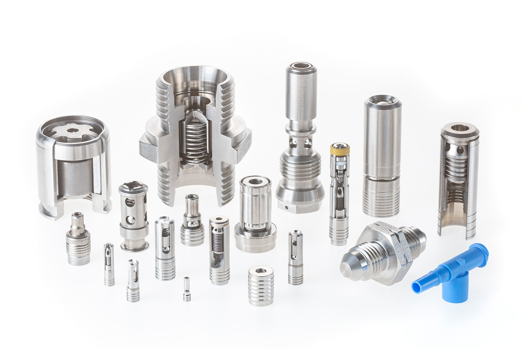
Configurations
Check valves are available in a variety of configurations. Common configurations feature a ball bearing, poppet, disc, or other seal held against a seat when pressure is in the checked direction. In many cases the seal will be biased into the position against the valve seat by a lightly loaded, compressed spring. The combination of these components creates the internal seal used to prevent ow in the checked direction.
There are many configurations for the internal ow path of spring-loaded check valves. For example, the fluid may flow axially between the ball or poppet and the interior of the valve housing; or it may ow through passages within a poppet down through the centre of the valve. Alternatively, some valve configurations allow flow to exit at 90 degrees relative to the valve inlet.
In low-pressure applications, a check valve may utilise a flexible material to control ow based on pressure conditions. The material may act as a basic diaphragm or in a duckbill configuration.
In high-flow hydraulic applications, butterfly and swing check valves are common. These valves use large, at metal doors attached to a housing that causes them to open with flow in one direction and shut in the checked direction.
If the application requires flow in the checked direction under certain conditions, the check valve may include additional features to force it open against pressure. Some check valves may include a feature that allows them to be manually piloted. Alternatively, one common configuration for hydraulic systems is a pilot-operated check valve. This is generally a three-port design in which the third port is connected to a pilot piston within the valve. Pressure is applied to this pilot port, and the pilot piston presses against the poppet to allow flow in the checked direction. When pressure is removed from the pilot port, the check valve will reseat and return to preventing flow in the checked direction.
There are several factors that must be considered to ensure the proper operation of a check valve within a system: system pressures, flow rate; leakage; cracking pressure; materials; and envelope. In addition, a number of environmental factors will impact the design of a check valve – such as operating fluid, operating life, temperature, external pressures, etc.
After determining the required performance characteristics of a check valve, it is critical to identify other variables that will influence the valve’s performance. The internal and external environment of the system will affect the valve’s performance in a variety of ways, impacting every aspect of its functionality and limiting options for the valve’s construction. When designing a valve, the following aspects of the system and environment must be considered: operating fluid; operating life; temperature; external pressures; vibration, shock and G-forces; and cleanliness.
Many industry associations have documented recommendations or requirements for the validation and verification of check valve performance to ensure safety within a specific system. Compliance to these specifications is usually required by governing bodies and passed down to suppliers of systems and components. When selecting a check valve, it is important to ensure it meets the industry standards required for the application.
The full guide is available in PDF format from The Lee Company: www.theleeco.com/resources/ebooks/an-engineers-guide-to-selecting-a-check-valve/
Lee Products www.leeproducts.co.uk
